20+ regulator block diagram
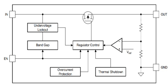
IC 723 Voltage Regulator. An example of a block diagram of a voltage regulator and the external resistors can be seen from the Texas Instruments LM317-N datasheet in Figure 3.
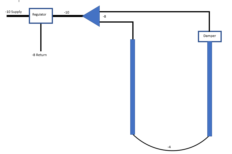
Fuel Pulse Dampers Mustang And Ford Performance Forums
A simple circuit for a typical directional switching regulator circuit is given in figure 26.
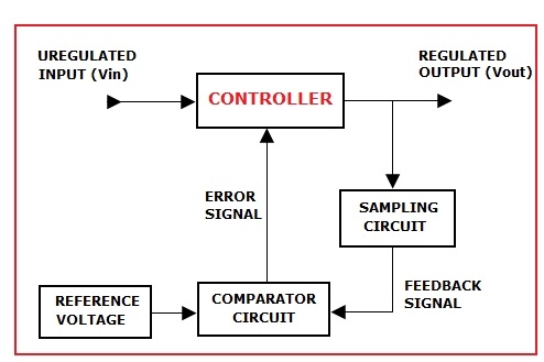
. 1 regulation with no wave form distortion. Back to FAQ Home Home. The basic block diagram of the series regulator circuit is shown below.
The pin diagram of IC 723. 67-72 wiring diagram. Wide range 10 -20 with standard DeltaDelta DeltaWye and WyeWye three phase designs.
The value of the output voltage is determined by the control environment. Back to FAQ Home. Functional Block Diagram For maximum design flexibility and minimum external part count the LM78S40 was designed to include all of the fundamental building blocks in an uncommitted.
IC 723 Functional Block Diagram Video Lecture from Voltage Regulator Chapter of Applied Electronics Subject for all Engineering StudentsAccess the Android. EMC performance of voltage regulator circuits is discussed in the following with reference to Fig1 where the block diagram of a linear voltage regulator is presented. The voltage regulator used in Figure 4 is often called a three terminal fixed voltage regulator.
The popular general purpose precision regulator is IC 723. Common output regulated voltages can be 5 6 8 12 15 18 24 volts etc. These 3-terminal regulators are incredibly easy to wire as can be viewed in the circuit diagram below that demonstrates the standard method by which these ICs are.
2016-12-20 TLS810B1xxV50 Ultra Low Quiescent Current Linear Voltage Regulator Overview Description The TLS810B1 is a linear voltage regulator featuring wide input voltage range low. It is a monolithic linear integrated circuit in different physical packages. A block diagram is a diagram of a system where the principal parts or functions are represented by blocks connected by lines that shows the relationships of the blocks.
In most of the applications due to irregular loads the. LM317 is a positive-voltage regulator with an adjustable voltage range from 125 V to 37 V. It can supply greater than 15 A at the output.
The control element is connected in series with the load in between ip and op terminal. The sampling circuit detects. 67-72 wiring diagram.

Circuit Diagram For The Variable High Voltage Power Supply Which Is Download Scientific Diagram
Tps7b81 Q1 Ldo Specifications And Applications

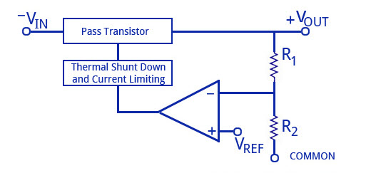
Ldo Voltage Regulator Circuit Source Ref 20 Download Scientific Diagram
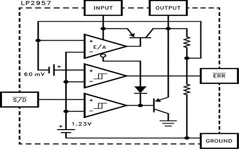
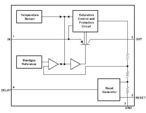
Lp2957 Block Diagram Specifications And Applications

Schematic Diagram Of The Automatic Voltage Regulator Download Scientific Diagram
Lm340 Series Voltage Regulators And Its Types

Efficiency Comparison For 72 V Input At A 20 Khz B 50 Khz Switching Download Scientific Diagram

Circuit Diagram For The Variable High Voltage Power Supply Which Is Download Scientific Diagram
Tle4275 Q1 Block Diagram Specifications Applications
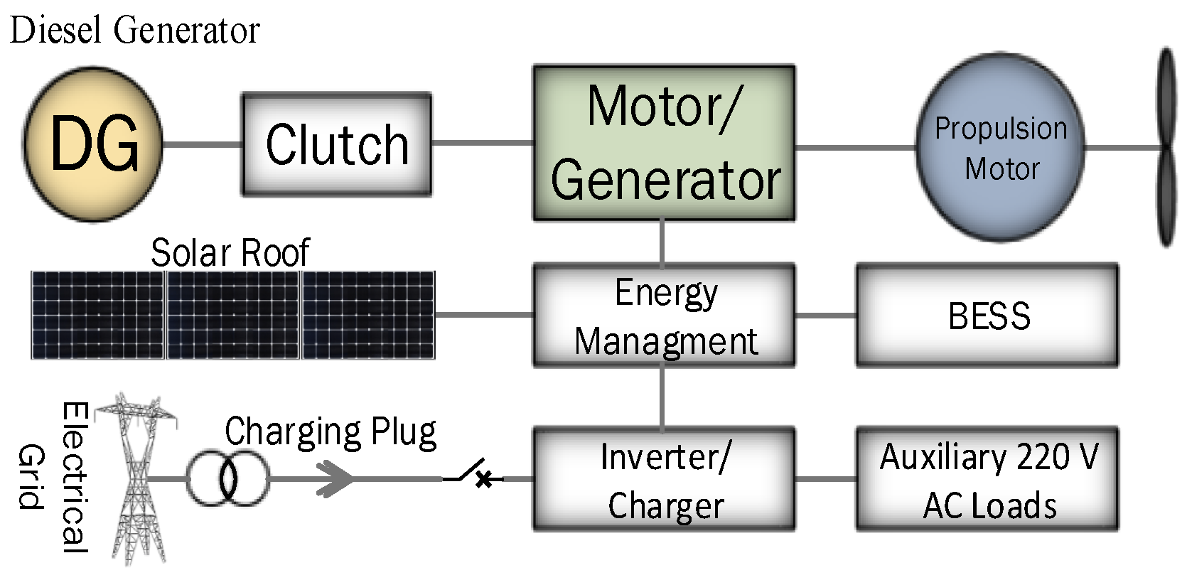
Energies Free Full Text Energy Storage Systems For Shipboard Microgrids A Review Html

Pin On Electronique
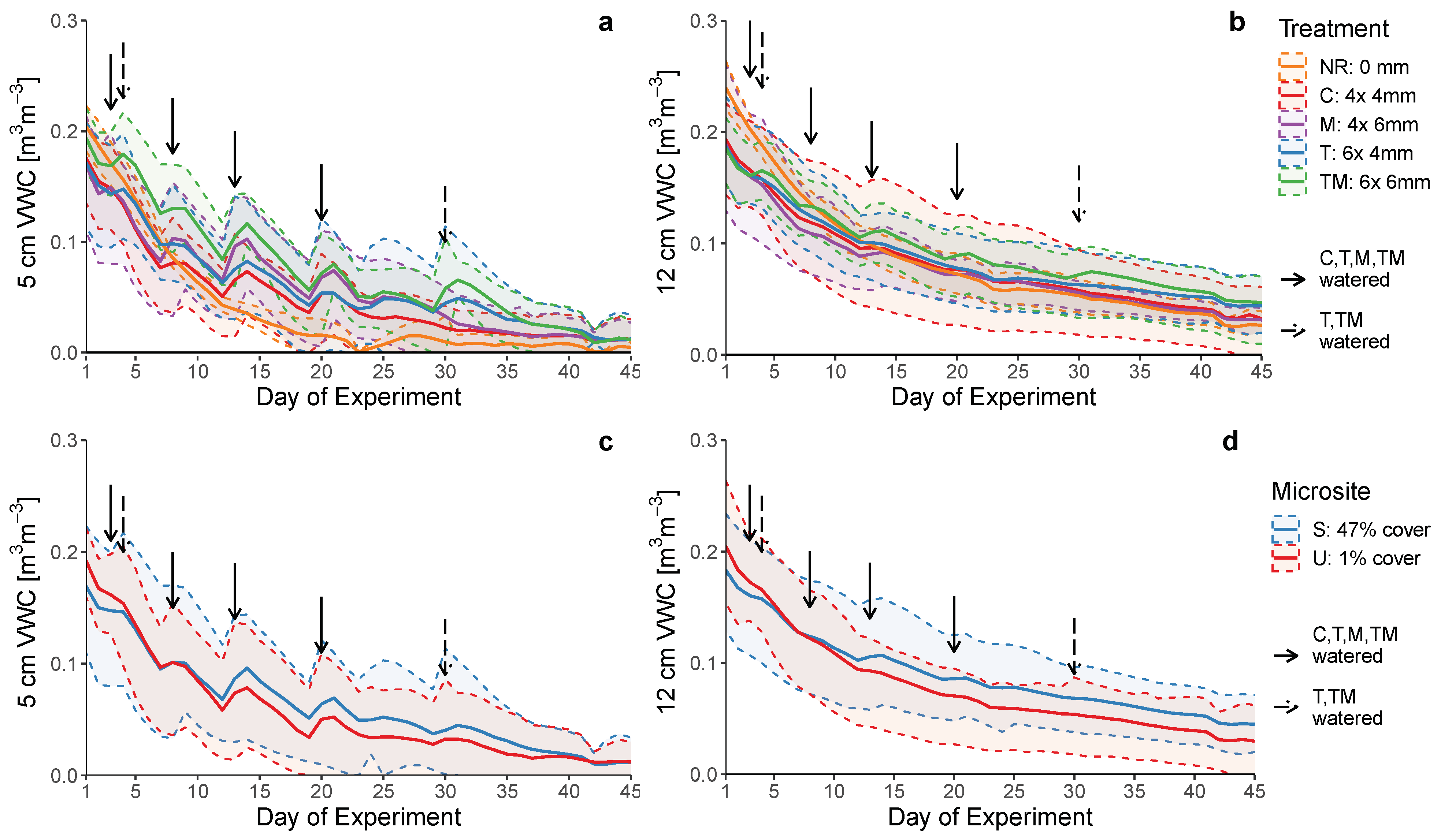
Forests Free Full Text Not Only Severe Events Moderate Dry Periods Impact The Hydraulic Functioning And Survival Of Planted Ponderosa Pine Seedlings Html

Download Stripboardmagic Free Circuitos Em Placas Padrao Https Www Te1 Com Br 2008 12 Programas Para D Circuito Impresso Eletronica Circuito Eletronico
![]()
The Proposed Voltage Regulator Transistor Level Circuit Topology Which Download Scientific Diagram

Schematic Diagram Of Voltage Regulator Circuit Download Scientific Diagram
Lm340 Series Voltage Regulators And Its Types

Conventional Topologies For Pmos Ldo Based On Flipped Voltage Follower Download Scientific Diagram